Assalamu‘alaikum wr. wb.
Hello guys, Kembali lagi bersama Inzaghi's Blog! Jika sebelumnya sudah pernah membahas tentang Implementasi Arduino ESP32 menggunakan Tinkercad, sekarang waktunya melakukan Implementasi Program Aplikasi Arduino Sederhana menggunakan Wokwi dan ESP32.
 |
| Ilustrasi Project ESP32 dengan Wokwi |
TUTORIAL CARA MENGGUNAKAN WOKWI
Pertama, merilah kita buka Situs Wokwi di sini (Wokwi.com). Kemudian, Masuklah menggunakan Akun Google.
Kemudian, Scroll ke bawah sampai menemukan "Start from Scratch". Kemudian pilih Arduino Uno.
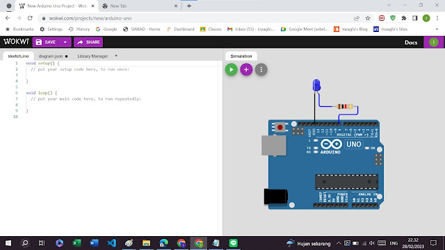
Maka akan seperti ini tampilannya :
Pada gambar di atas, terdapat bagian :
a. sketch.ino
Di bagian ini kita dapat mengetikkan code untuk mengontrol kerja MCU kita.
b. diagram.json
Bagian ini merupkan jantungnya koneksi. Di sini kita memanggil semua elemen yang akan kita gunakan dan memberitahukan kepada simulator Wokwi bagaimana untuk menghubungkan mereka.
c. Library Manager
Bagian ini untuk menambahkan Pustaka/Library dari Komponen yang belum ada di Wokwi.
d. Simulation
Pada bagian ini ada 3 Icon, yaitu :
- Icon ▶ untuk menjalankan simulasi.
- Icon ➕ untuk menambahkan komponen ke jendela simulator.
- Icon ⋮ untuk menampilkan menu untuk zoom, full screen, dsb.
Lalu, kik pada Ikon Plus (➕) untuk menambahkan Bagian Komponen. Kita akan menambahkan Resistor dan LED.
Maka akan seperti ini hasilnya :
Selanjutnya, kita ganti Warna Lampu LED tersebut menjadi Biru. Dan Klik pada Kaki Katoda dan lakukan Drag and Drop pada Pin GND untuk menghubungkan Kaki Katoda LED ke Arduino Uno.
Maka kaki Katoda LED akan terhubung ke GND dari MCU.
Untuk mengganti Warna Kabel Jumper, klik pada kabel tersebut. Kemudian pilih Warna, dan
Ganti dengan Warna Hitam.
Kemudian, Rangkailah LED dan Resistor dengan MCU menjadi seperti Gambar berikut :
void setup() {// put your setup code here, to run once:pinMode(8, OUTPUT);}void loop() {// put your main code here, to run repeatedly:digitalWrite(8, LOW);delay(5000);digitalWrite(8, HIGH);delay(2000);}
Di Wokwi tidak semudah seperti di Tinkercad untuk menggeser Rotasi dari sebuah benda. Di Wokwi, kita haus menggunakan Kode JSON untuk memindahkan Rotasi dari sebuah benda. Untuk mempelajari tentang Kode JSON di Wokwi, silakan lihat di sini.
Misalnya, jika kita ingin menggeser sebuah Resistor yang semulanya Horizontal menjadi Vertikal, maka kita harus menambahkan Kode JSON pada Kode berikut ini :
"rotate": 90
Sehingga, akan menjadi seperti ini :
{"type": "wokwi-resistor","id": "r1","top": 190.23,"left": 180.64,"rotate": 90,"attrs": { "value": "1000" }},
Untuk selengkapnya, lihat di sini (Diagram Format). Dan inilah hasilnya :
Terakhir jika sudah selesai, sekarang kita simpan Project yang telah kita lakukan dengan mengeklik di Tombol "Save" kemudian ketiklah pada Kolom "Save Your Project". Setelah itu, klik "Save".
MEMBUAT RANGKAIAN DAN KODE ARDUINO DENGAN MENGGUNAKAN WOKWI
Sumber Tutorial (ESP32) : ESP32io.com
Sumber Tutorial Lainya (Arduino Uno) : Arduinogetstarted.com
Sama seperti di Tinkercad, di Wokwi juga hampir sama untuk membuat Proyek Sistem Terbenam dan IoT. Akan tetapi, untuk di Wokwi kita lebih memilih untuk menggunakan ESP32 daripada Arduino Uno, kecuali beberapa Proyek sederhana yang memerlukan Tegangan 5V.
1. Arduino Dasar
1. Hello World
Kode :
void setup() {// put your setup code here, to run once:Serial.begin(115200);Serial.println("Hello World!");}void loop() {// put your main code here, to run repeatedly:delay(10); // this speeds up the simulation}
Gambar :
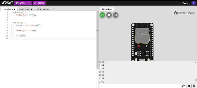
2. Analog Waves (Serial Plotter)
Kode :
void setup() {Serial.begin(9600);}void loop() {int y1 = analogRead(A0);Serial.println(y1);delay(100);}
Gambar :
Gambar :
Kode :
void setup(){pinMode(25, OUTPUT);}void loop(){digitalWrite(25, HIGH);delay(1000); // Wait for 1000 millisecond(s)digitalWrite(25, LOW);delay(1000); // Wait for 1000 millisecond(s)}
3. LED Breadboard dengan Tombol (Blinking LED with Button)
Gambar :
Kode :
// constants won't change:const int LED_PIN = 27; // the number of the LED pinconst int BUTTON_PIN = 33; // the number of the button pinconst long BLINK_INTERVAL = 1000; // interval at which to blink LED (milliseconds)// Variables will change:int ledState = LOW; // ledState used to set the LEDint previousButtonState = LOW; // will store last time button was updatedunsigned long previousMillis = 0; // will store last time LED was updatedvoid setup() {Serial.begin(9600);// set the digital pin as output:pinMode(LED_PIN, OUTPUT);// set the digital pin as an input:pinMode(BUTTON_PIN, INPUT);}void loop() {unsigned long currentMillis = millis();if (currentMillis - previousMillis >= BLINK_INTERVAL) {// if the LED is off turn it on and vice-versa:ledState = (ledState == LOW) ? HIGH : LOW;// set the LED with the ledState of the variable:digitalWrite(LED_PIN, ledState);// save the last time you blinked the LEDpreviousMillis = currentMillis;}// check button state's changeint currentButtonState = digitalRead(BUTTON_PIN);if(currentButtonState != previousButtonState) {// print out the state of the button:Serial.println(currentButtonState);// save the last state of buttonpreviousButtonState = currentButtonState;}}
4. LED Breadboard Tanpa Delay (Blinking LED Without Delay)
Gambar :
Kode :
// constants won't change:const int LED_PIN = 27; // the number of the LED pinconst int BUTTON_PIN = 33; // the number of the button pin#define BLINK_INTERVAL 1000 // interval at which to blink LED (milliseconds)// Variables will change:int ledState = LOW; // ledState used to set the LEDint previousButtonState = LOW; // will store last time button was updatedvoid setup() {Serial.begin(9600);// set the digital pin as output:pinMode(LED_PIN, OUTPUT);// set the digital pin as an input:pinMode(BUTTON_PIN, INPUT_PULLUP);}void loop() {// if the LED is off turn it on and vice-versa:ledState = (ledState == LOW) ? HIGH : LOW;// set the LED with the ledState of the variable:digitalWrite(LED_PIN, ledState);delay(BLINK_INTERVAL); // If button is pressed during this time, Arduino CANNOT detectint currentButtonState = digitalRead(BUTTON_PIN);if (currentButtonState != previousButtonState) {// print out the state of the button:Serial.println(currentButtonState);// save the last state of buttonpreviousButtonState = currentButtonState;}// DO OTHER WORKS HERE}
3. Lampu LED RGB
Gambar :
Kode :
#define PIN_RED 18#define PIN_GREEN 19#define PIN_BLUE 21void setup() {pinMode(PIN_RED, OUTPUT);pinMode(PIN_GREEN, OUTPUT);pinMode(PIN_BLUE, OUTPUT);}void loop() {// color code #00C9CC (R = 0, G = 201, B = 204)analogWrite(PIN_RED, 0);analogWrite(PIN_GREEN, 201);analogWrite(PIN_BLUE, 204);delay(1000); // keep the color 1 second// color code #F7788A (R = 247, G = 120, B = 138)analogWrite(PIN_RED, 247);analogWrite(PIN_GREEN, 120);analogWrite(PIN_BLUE, 138);delay(1000); // keep the color 1 second// color code #34A853 (R = 52, G = 168, B = 83)analogWrite(PIN_RED, 52);analogWrite(PIN_GREEN, 168);analogWrite(PIN_BLUE, 83);delay(1000); // keep the color 1 second}
4. Potentiometer
Kode :
#define POTENTIOMETER_PIN 35 // ESP32 pin GIOP36 (ADC0) connected to Potentiometer pin#define LED_PIN 21 // ESP32 pin GIOP21 connected to LED's pin#define ANALOG_THRESHOLD 1000void setup() {pinMode(LED_PIN, OUTPUT); // set ESP32 pin to output mode}void loop() {int analogValue = analogRead(POTENTIOMETER_PIN); // read the input on analog pinif (analogValue > ANALOG_THRESHOLD)digitalWrite(LED_PIN, HIGH); // turn on LEDelsedigitalWrite(LED_PIN, LOW); // turn off LED}
Kode :
#include <Servo.h>Servo myServo; // create servo object to control a servovoid setup() {// initialize serial communication at 9600 bits per second:Serial.begin(9600);myServo.attach(5); // attaches the servo on pin 5 to the servo object}void loop() {// reads the value of the potentiometer (value between 0 and 1023)int analogValue = analogRead(A0);// scales it to use it with the servo (value between 0 and 180)int angle = map(analogValue, 0, 1023, 0, 180);// sets the servo position according to the scaled valuemyServo.write(angle);// print out the valueSerial.print("Analog: ");Serial.print(analogValue);Serial.print(", Angle: ");Serial.println(angle);delay(100);}
5. Sensor Ultrasonik
1. Sensor Ultrasonik dengan LED
Gambar :
Kode :
#define TRIG_PIN 18 // ESP32 pin connected to Ultrasonic Sensor's TRIG pin#define ECHO_PIN 19 // ESP32 pin connected to Ultrasonic Sensor's ECHO pin#define LED_PIN 21 // ESP32 pin connected to LED's pin#define DISTANCE_THRESHOLD 50 // centimeters// variables will change:float duration_us, distance_cm;void setup() {Serial.begin (9600); // initialize serial portpinMode(TRIG_PIN, OUTPUT); // set ESP32 pin to output modepinMode(ECHO_PIN, INPUT); // set ESP32 pin to input modepinMode(LED_PIN, OUTPUT); // set ESP32 pin to output mode}void loop() {// generate 10-microsecond pulse to TRIG pindigitalWrite(TRIG_PIN, HIGH);delayMicroseconds(10);digitalWrite(TRIG_PIN, LOW);// measure duration of pulse from ECHO pinduration_us = pulseIn(ECHO_PIN, HIGH);// calculate the distancedistance_cm = 0.017 * duration_us;if (distance_cm < DISTANCE_THRESHOLD)digitalWrite(LED_PIN, HIGH); // turn on LEDelsedigitalWrite(LED_PIN, LOW); // turn off LED// print the value to Serial MonitorSerial.print("distance: ");Serial.print(distance_cm);Serial.println(" cm");delay(500);}
2. Sensor Ultrasonik dengan Servo Motor (Arduino Uno)
Gambar :
Kode :
#include <Servo.h>// constants won't changeconst int TRIG_PIN = 4; // Arduino pin connected to Ultrasonic Sensor's TRIG pinconst int ECHO_PIN = 6; // Arduino pin connected to Ultrasonic Sensor's ECHO pinconst int SERVO_PIN = 3; // Arduino pin connected to Servo Motor's pinconst int DISTANCE_THRESHOLD = 50; // centimetersServo servo; // create servo object to control a servo// variables will change:float duration_us, distance_cm;void setup() {Serial.begin (9600); // initialize serial portpinMode(TRIG_PIN, OUTPUT); // set arduino pin to output modepinMode(ECHO_PIN, INPUT); // set arduino pin to input modeservo.attach(SERVO_PIN); // attaches the servo on pin 9 to the servo objectservo.write(0);}void loop() {// generate 10-microsecond pulse to TRIG pindigitalWrite(TRIG_PIN, HIGH);delayMicroseconds(10);digitalWrite(TRIG_PIN, LOW);// measure duration of pulse from ECHO pinduration_us = pulseIn(ECHO_PIN, HIGH);// calculate the distancedistance_cm = 0.017 * duration_us;if(distance_cm < DISTANCE_THRESHOLD)servo.write(90); // rotate servo motor to 90 degreeelseservo.write(0); // rotate servo motor to 0 degree// print the value to Serial MonitorSerial.print("distance: ");Serial.print(distance_cm);Serial.println(" cm");delay(500);}
6. PIR Sensor (Sensor Gerak / Motion Sensor)
1. PIR Sensor dengan LED (Arduino Uno)
Gambar :
Kode :
const int MOTION_SENSOR_PIN = 10; // Arduino pin connected to the OUTPUT pin of motion sensorconst int LED_PIN = 5; // Arduino pin connected to LED's pinint motionStateCurrent = LOW; // current state of motion sensor's pinint motionStatePrevious = LOW; // previous state of motion sensor's pinvoid setup() {Serial.begin(9600); // initialize serialpinMode(MOTION_SENSOR_PIN, INPUT); // set arduino pin to input modepinMode(LED_PIN, OUTPUT); // set arduino pin to output mode}void loop() {motionStatePrevious = motionStateCurrent; // store old statemotionStateCurrent = digitalRead(MOTION_SENSOR_PIN); // read new stateif (motionStatePrevious == LOW && motionStateCurrent == HIGH) { // pin state change: LOW -> HIGHSerial.println("Motion detected!");digitalWrite(LED_PIN, HIGH); // turn on}elseif (motionStatePrevious == HIGH && motionStateCurrent == LOW) { // pin state change: HIGH -> LOWSerial.println("Motion stopped!");digitalWrite(LED_PIN, LOW); // turn off}}
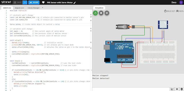
2. PIR Sensor dengan Servo Motor (Arduino Uno)
Gambar :
Kode :
#include <Servo.h>// constants won't changeconst int MOTION_SENSOR_PIN = 6; // Arduino pin connected to motion sensor's pinconst int SERVO_PIN = 9; // Arduino pin connected to servo motor's pinServo servo; // create servo object to control a servo// variables will change:int angle = 0; // the current angle of servo motorint lastMotionState; // the previous state of motion sensorint currentMotionState; // the current state of motion sensorvoid setup() {Serial.begin(9600); // initialize serialpinMode(MOTION_SENSOR_PIN, INPUT); // set arduino pin to input modeservo.attach(SERVO_PIN); // attaches the servo on pin 9 to the servo objectservo.write(angle);currentMotionState = digitalRead(MOTION_SENSOR_PIN);}
void loop() {lastMotionState = currentMotionState; // save the last statecurrentMotionState = digitalRead(MOTION_SENSOR_PIN); // read new stateif (currentMotionState == LOW && lastMotionState == HIGH) { // pin state change: LOW -> HIGHSerial.println("Motion detected!");servo.write(90);}elseif (currentMotionState == HIGH && lastMotionState == LOW) { // pin state change: HIGH -> LOWSerial.println("Motion stopped!");servo.write(0);}}
7. LCD Display
1. LCD Display (Arduino Uno)
Gambar :
Kode :
#include <LiquidCrystal.h>// LCD pins <--> Arduino pinsconst int RS = 11, EN = 10, D4 = 2, D5 = 3, D6 = 4, D7 = 5;LiquidCrystal lcd(RS, EN, D4, D5, D6, D7);void setup(){lcd.begin(16, 2); // set up number of columns and rows}void loop(){lcd.setCursor(0, 0); // move cursor to (0, 0)lcd.print("Inzaghi's Blog"); // print message at (0, 0)lcd.setCursor(2, 1); // move cursor to (2, 1)lcd.print("Inzaghi.com"); // print message at (2, 1)}
2. LCD I2C (Arduino Uno)
Gambar :
Kode :
#include <LiquidCrystal_I2C.h>LiquidCrystal_I2C lcd(0x27, 16, 2); // I2C address 0x27, 16 column and 2 rowsvoid setup(){lcd.init(); // initialize the lcdlcd.backlight();}void loop(){lcd.clear(); // clear displaylcd.setCursor(0, 0); // move cursor to (0, 0)lcd.print("Inzaghi Blog"); // print message at (0, 0)lcd.setCursor(2, 1); // move cursor to (2, 1)lcd.print("enzatech.com"); // print message at (2, 1)delay(2000); // display the above for two secondslcd.clear(); // clear displaylcd.setCursor(3, 0); // move cursor to (3, 0)lcd.print("Inzaghi Sites"); // print message at (3, 0)lcd.setCursor(0, 1); // move cursor to (0, 1)lcd.print("www.inzaghi.com"); // print message at (0, 1)delay(2000); // display the above for two seconds}
8. Buzzer
1. Buzzer dengan Tombol (Buzzer with Button)
Gambar :
Kode :
#define BUTTON_PIN 19#define BUZZER_PIN 21void setup() {Serial.begin(9600); // initialize serialpinMode(BUTTON_PIN, INPUT_PULLUP); // set ESP32 pin to input pull-up modepinMode(BUZZER_PIN, OUTPUT); // set ESP32 pin to output mode}void loop() {int buttonState = digitalRead(BUTTON_PIN); // read new stateif (buttonState == LOW) {Serial.println("The button is being pressed");digitalWrite(BUZZER_PIN, HIGH); // turn on}elseif (buttonState == HIGH) {Serial.println("The button is unpressed");digitalWrite(BUZZER_PIN, LOW); // turn off}}
2. Buzzer dengan Potentiometer (Buzzer with Potentiometer)
Gambar :
Kode :
#define POTENTIOMETER_PIN 32#define BUZZER_PIN 21#define ANALOG_THRESHOLD 1000void setup() {pinMode(BUZZER_PIN, OUTPUT); // set ESP32 pin to output mode}void loop() {int analogValue = analogRead(POTENTIOMETER_PIN); // read the input on analog pinif (analogValue > ANALOG_THRESHOLD)digitalWrite(BUZZER_PIN, HIGH); // turn on Piezo BuzzerelsedigitalWrite(BUZZER_PIN, LOW); // turn off Piezo Buzzer}
3. Buzzer dengan Sensor Ultrasonik (Buzzer with Ultrasonic Sensor)
Gambar :
Kode :
#define TRIG_PIN 18 // ESP32 pin GIOP18 connected to Ultrasonic Sensor's TRIG pin#define ECHO_PIN 32 // ESP32 pin GIOP32 connected to Ultrasonic Sensor's ECHO pin#define BUZZER_PIN 19 // ESP32 pin GIOP19 connected to Piezo Buzzer's pin#define DISTANCE_THRESHOLD 50 // centimeters// variables will change:float duration_us, distance_cm;void setup() {Serial.begin (9600); // initialize serial portpinMode(TRIG_PIN, OUTPUT); // set ESP32 pin to output modepinMode(ECHO_PIN, INPUT); // set ESP32 pin to input modepinMode(BUZZER_PIN, OUTPUT); // set ESP32 pin to output mode}void loop() {// generate 10-microsecond pulse to TRIG pindigitalWrite(TRIG_PIN, HIGH);delayMicroseconds(10);digitalWrite(TRIG_PIN, LOW);// measure duration of pulse from ECHO pinduration_us = pulseIn(ECHO_PIN, HIGH);// calculate the distancedistance_cm = 0.017 * duration_us;if (distance_cm < DISTANCE_THRESHOLD)digitalWrite(BUZZER_PIN, HIGH); // turn on Piezo BuzzerelsedigitalWrite(BUZZER_PIN, LOW); // turn off Piezo Buzzer// print the value to Serial MonitorSerial.print("distance: ");Serial.print(distance_cm);Serial.println(" cm");delay(500);}
4. Buzzer dengan PIR Sensor (Buzzer with PIR Sensor)
Gambar :
Kode :
#define MOTION_SENSOR_PIN 21 // ESP32 pin GIOP21 connected to the OUTPUT pin of motion sensor#define BUZZER_PIN 19 // ESP32 pin GIOP19 connected to Buzzer's pinint motionStateCurrent = LOW; // current state of motion sensor's pinint motionStatePrevious = LOW; // previous state of motion sensor's pinvoid setup() {Serial.begin(9600); // initialize serialpinMode(MOTION_SENSOR_PIN, INPUT); // set ESP32 pin to input modepinMode(BUZZER_PIN, OUTPUT); // set ESP32 pin to output mode}void loop() {motionStatePrevious = motionStateCurrent; // store old statemotionStateCurrent = digitalRead(MOTION_SENSOR_PIN); // read new stateif (motionStatePrevious == LOW && motionStateCurrent == HIGH) { // pin state change: LOW -> HIGHSerial.println("Motion detected!, making sound");digitalWrite(BUZZER_PIN, HIGH); // turn on} else if (motionStatePrevious == HIGH && motionStateCurrent == LOW) { // pin state change: HIGH -> LOWSerial.println("Motion stopped!, stops making sound");digitalWrite(BUZZER_PIN, LOW); // turn off}}
Dan masih banyak lagi Proyek-proyek Arduino lainnya yang bisa kamu coba dengan menggunakan Wokwi. Anda juga bisa menggunakan MCU lainnya seperti ESP8266 atau bahkan Arduino Uno pada Wokwi.
Untuk melihat Artikel sebelumnya tentang Program Arduino menggunakan Tinkercad, silakan lihat di sini.
Terima Kasih 😄😘👌👍 :)
Wassalamu‘alaikum wr. wb.

.jpg)


.jpg)

.jpg)
.jpg)
.jpg)
.jpg)
.jpg)
.jpg)
.jpg)
.jpg)
.jpg)
.jpg)
.jpg)
.jpg)
.jpg)
.jpg)
.jpg)
.jpg)
.jpg)
.jpg)
.jpg)